
How To Add T-Track Clamps and a New Z-Axis to an X-Carve CNC
I know I want to do more with my Inventables X-Carve this year, so I added a bunch of upgrades to the machine, including Rockler t-track for better clamping and workholding, as well as a raised X-axis and brand new Z-axis. With these new upgrades, I can cut pieces up to 4 inches thick on the X-Carve, at speeds I was previously unable to achieve!
🤖 Learn more about my Inventables X-Carve CNC :
Check out all of the upgrades I added from TBDCNC (listed below) :
Ultimate Upgrade Kit with 2” Risers and Stiffeners
2GT 9mm Belt Upgrade Kit
Supergrade Z-Axis
15mm Z Axis Upgrade

Pin It!
Process For Upgrading Your CNC:
Step 1: Assess The Current Issues With Your CNC
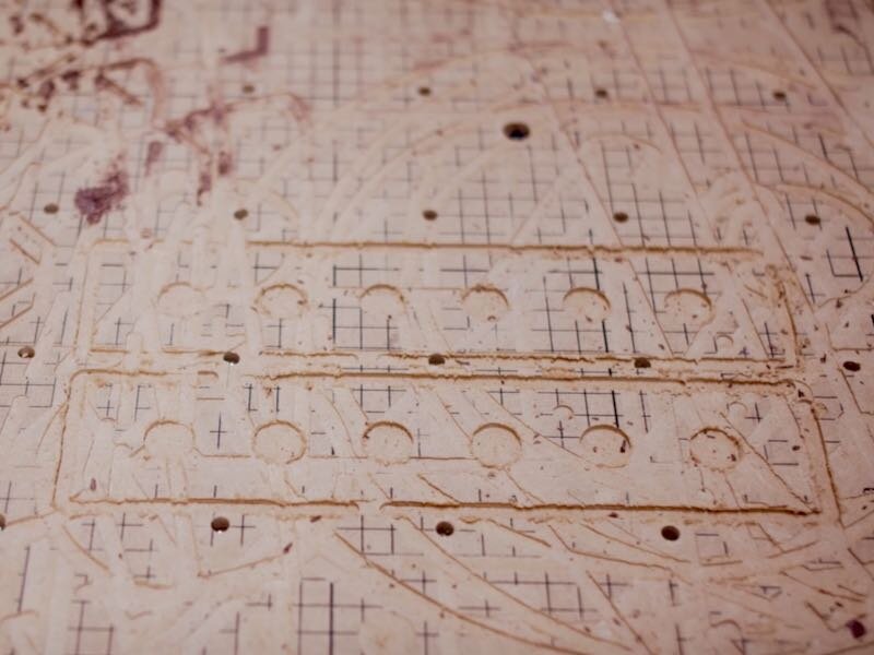
This whole project started because the spoilboard on my X-Carve was getting pretty beat up. When I first started using the machine, I wasn’t really concerned with precision when it came to entering the thickness of the things I was cutting and, because of that, I ended up with my spoilboard looking like it had been in battle.
Now, the obvious solution was to flatten the spoilboard and get it looking fresh again, but this posed a problem. You see, the spoilboard on the X-Carve is bigger than its cutting area, so skimming off an ⅛” would cause there to be a sunken area in the middle of the board, with the edges still at their original thickness.

This isn’t a problem most of the time, but if I wanted to hang a piece off of the front or back of the X-Carve while cutting, this would no longer be possible.
I knew that, as part of this project, I wanted to improve the X-Carve’s workholding capabilities anyway, so I figured adding some MDF strips on top of the existing spoilboard, with t-track running between those strips, would be the perfect solution. The added strips would raise the workpiece, so that I could hang pieces off the front if needed, and the t-track would allow tons of options for fixturing and workholding.
Step 2: Preparing A New Spoil Board For CNC Platform

I cut some strips of scrap MDF at the table saw, making sure to leave them oversized so I could trim them to final size on the X-Carve, and then marked hole locations which lined up with the threaded inserts on the X-Carve’s spoilboard. I wanted these strips to be easily replaceable if and when they get damaged, and using the inserts to attach the strips was the perfect solution.
I drilled some recessed holes at the drill press, first recessing the hole with a Forstner bit and then coming back with a twist bit to drill the through hole. I originally only drilled two holes at each end of the strips, but I ended up coming back and adding two more holes at the center of the strips as well.

To attach the strips to the spoilboard, I used these pan head machine screws, and having the holes in the strips lined up with the threaded inserts made the installation process super quick.
Step 3: Mounting The New Spoil Board To CNC Platform

As you can see, the slots between the strips are way too small for t-track, but that was on purpose, because I wanted to cut those to fit.
The next step was to widen those slots, which I really took my time with, as I wanted a tight fit with the t-track. I initially made extremely shallow passes until I got a perfect fit, and any of those shallow passes that were too wide were cleaned up when I surfaced the strips later.
After getting the fit just right, I ran the full operation, making sure I dialed in my depth so the bit didn’t dig into the fresh spoilboard.
Next, I needed to square up the front and back edges of the strips, and it’s a good idea to make absolutely sure your gantry is nice and square before performing an operation like this. I like to use a spacer on each side of the rail, pulling it snug against the spacer, and then turning the machine on. This locks it into place and confirms the carriage isn’t out of square.
With the gantry square, I squared up the front and back edges of the strips and then surfaced the strips to get them perfectly flat.

The last bit of work on these strips was to add some lines to indicate where each inch of surface area was, and this also will help to line things up quickly in the future when I’m clamping material to the spoilboard. This was a tip I picked up from one of Jay Bates’ recent CNC videos, which have been super informative, and I’ll add a card so you can check that out.
Next, I could get the t-track installed and try out some clamps, and that’s where I discovered I had an issue.
Step 4: Improving The Z-axis Among Other Upgrades For The X-Carve

The clamps I wanted to use on my T-track would not allow clearance for the machine so I did some searching online and found TBD CNC. This is where I obtain some serious upgrades for my X-carve.
The first step before installing these new upgrades was to remove the strips and spoilboard I just finished installing, but luckily these were easy to remove and could be reused later.
The first upgrade item I installed were these riser plates which raise the Y-axis rails two inches and also provide extra clearance for the dust boot. The risers also come with new, beefier bolts, which just reduce the likelihood of stripping these bolts later on.

I added the riser plate at the front, only attaching the bottom two bolts to start, and then repeated the process at the back. I made sure to prop up the rail to keep the gantry from getting tweaked during this process. I could then lift the rail up and install the two top bolts at each end of the rail. And I just repeated this on the other side of the X-Carve in the same way.
Next, I could install these stiffeners, which connect the base extrusion to the Y axis rails and keep them from flexing under heavy load. These just attach with a few tee nuts, but you do need to remove the base rails to insert these tee nuts.

Each stiffener has one bolt at the bottom and two at the top, and I used four stiffeners per side, which resulted in an incredibly stiff Y-axis rail.
The next upgrade to work on was this new Supergrade Z-axis from TBDCNC. This replacement Z-Axis runs on linear rails, meaning it’s super precise, and it gives you 6” of Z-axis travel, vs. the 2 ½” of stock travel. This will allow me to cut much thicker pieces on the X-Carve, and it will allow cutting much deeper operations on those pieces.
The upgrade is pretty simple and really just drops into place, and it reuses a lot of the stock parts from the X-Carve. One other thing I added to the Supergrade that wasn’t stock was this more robust 15mm belt, which will give the Z-axis a little more oomph and stability.

Finally, I could get the router mounting plate reinstalled on the new Z-axis, which just mounts with a few bolts.

In order to reinstall the spoilboard, I needed to trim down its width slightly, taking ⅛” off of each side. This allowed the spoilboard to fit between those new stiffeners, and I did have to re-drill the mounting holes on the two sides of the spoilboard to accommodate this slightly narrower width.
Step 5: Adding T-track To The Spoil Board Of The CNC

Next, I reinstalled the MDF strips, making sure they were in the same orientation as when I removed them, and then I could start working on getting the Rockler t-track installed.
First, I needed to trim the t-track, which comes in one foot increments, down to a length of 29 ½”. I made sure to remove some material from both ends, to ensure I had a screw hole at each end of the t-track sections. I really didn’t want these pieces coming loose under clamping pressure, and having evenly spaced screws will help with that.
To cut the t-track, I used my portaband on this sweet new SWAG Off Road stand I picked up, but a hacksaw or even a regular miter saw cuts aluminum just fine. I just didn’t want aluminum shavings all over my miter saw station.

After cutting, I was left with pretty sharp edges on the t-track, so I sanded down these areas with my belt grinder, but again a simpler solution would be a file.
To install the t-track, I positioned it flush with the ends of the strips, pre-drilled the holes using a self-centering bit, and drove in ⅝” long screws to hold it down. I added double sided tape to the first few pieces of t-track, thinking it might improve the holding power, but I decided about halfway through this probably wasn’t necessary.
Step 6: Final Upgrades To X-Carve
Once the t-track was installed, I could mess around with some of the t-track accessories I got for the CNC. I did have to add longer bolts to some of the accessories to work with this setup. The MDF strips are proud of the t-track, so that I won’t accidentally cut into it with my router, but usually t-track is flush with the work surface, and that’s how these accessories are designed to work. A slightly longer bolt solves this issue though, and Rockler has a ton of different bolt lengths available for these accessories.
Alright, in the home stretch now as far as upgrades! Next on the list was an upgraded belt system, again from TBDCNC. I first needed to remove the existing belts and clips from the X-Carve, as well as swap out the idler rollers to accept the bigger belts.
The belt kit comes with new, stronger clips and installs just like the original X-Carve belts did. These more robust belts should keep the X-Carve more rigid when it’s cutting aggressively, and, since they’re beefier, they’re less likely to break.
The last upgrade to install on the X-Carve was this new dust shoe called the Magnaboot, made by Yellowbox Shed. This dust shoe is entirely 3D printed, which I think is super cool, and the height is easily adjustable by moving the shoe up or down one level on the rare earth magnets that hold it in place.

The Magnaboot also utilizes 4” flex hose, which provides a ton more suction than the stock dust boot, and I was able to rig the boom arm that came with my X-Carve for use with this 4” hose.
With the upgrades to the X-Carve done, I figured I’d finish things up by adding some better storage to the stand that my X-Carve lives on, which is just a Rockler shop stand with two layers of OSB on top
First, to organize the plethora of t-track accessories, I added two of these t-track racks to the side of the table.

I’ve had this leftover double layered OSB from back when I had a deadlifting platform in this garage, and I figured the other leftover piece would make the perfect bottom shelf for this stand. The top is super rigid, even with no center support, so it should be good enough for the bottom too.
I cut the OSB to size and added a few screws from below to hold it in place.
I will probably come back and add drawers later, but this is good enough for now, and allows the machine to be rolled around freely.
Step 7: Calibrating CNC Machine

With all of that done, I could finally fire up the X-Carve for the first time since adding all of these upgrades and make sure I reinstalled everything correctly.
Before homing the machine, I needed to update the step value for the Z-Axis, since it’s a completely new unit.
Once that was finished, I could home the machine and everything seemed to be working, which was super exciting.
Before actually cutting anything, I needed to recalibrate all three axes, to account for the new belt sizes. This is a fairly simple process and there are some great videos out there on how this is done, which I’ll link to in the video description, but you basically just give the X-Carve a set distance to travel, measure the distance it actually traveled, and then enter that new value in the Machine Inspector section of Easel.

With that done, it was time to get to cutting!
To do the test cuts, I switched over to this ¼” compression bit from Infinity Tools. I’m a big fan of compression bits on the CNC, as they’re basically a combination of an upcut and downcut spiral bit and usually leave a great surface finish.
I got a scrap piece of plywood clamped down, zeroed the machine, and set up a simple operation which would cut a circle, starting at 100 inches per minute, cutting .1 inches on each pass.
After the cut finished up, I checked out the piece and was left with a basically perfect cut, so I decided to bump the feed rate up to 120 inches per minute and the depth of cut to about ⅛”.
Once again, the machine had no trouble with this and cut very smoothly, and I was left with a perfect cut.

The last test was to ensure the machine would still cut square at these increased speeds, and I confirmed that by cutting a small square and checking it with a square.
With the testing done, I could finally call this project complete!
--