
Workshop Renovation Part 4 : Framing Walls & Floor Platform
In part 4 of my dream workshop renovation, we frame a room for my CNC plus build a wooden platform to cover up some issues in the floor.
🛠 Tools Used :
Materials Used :
Framing Walls and Building a Floor Platform in the New Workshop
As you might have noticed, the big move from the old shop happened between these last two videos, so the first thing we needed to do once the Perkins guys arrived was move my monster AVID CNC out of our way.

I picked up these cheap little 3 wheel dollies from Harbor Freight and they were perfect for moving the CNC around.
Step 1: Layout and Install Bottom and Top Plates
Once the CNC was out of the way, Ray and Jason started laying out the location of the bottom plates using the 3-4-5 method to make sure the plate was square to the wall.
With the location figured out, we got the plate attached to the floor with a few concrete anchors, and once again that SDS drill really came in handy during this part of the project.

While Jason got the bottom plate installed, Erik started measuring for blocking, which needed to be installed since the top plate was going to land between two floor joists. We were able to use up a lot of the material we had demoed in the attic space for this blocking, and I loved not having to send all of this material to the landfill.

We snapped a line for the second bottom plate and got that installed while Erik and Ray started laying out the door opening on the other wall.
We transferred the stud layout to the top plate and then got that installed on the ceiling, plumbing the two plates with each other using a long, straight board and a line laser.

Step 2: Fill in Studs for CNC Room Walls
Once the plate was installed, we could start filling in the studs, cutting them to fit, as once again, this slab is not perfectly flat.
For the door opening, I ended up going with roughly 7 feet wide and just under 8 feet tall. This should allow me to easily get full sheets of plywood loaded onto the CNC, and the doors will open inward and swing completely out of the way, against the wall. I’ll be building these doors so I can add soundproofing insulation to them to help keep the noise from the CNC isolated in this room.

Also, in case you’re wondering, the dimensions of the room are 12 feet wide by 15 feet deep.
Once the front wall was framed, we repeated the process to frame the side wall, and all of this framing material was pulled out of my old shop, and I’ll be covering the process of moving my tools and demoing the old shop in next week’s video.
With that, the CNC room was framed, so we could move on to the platform. We needed to frame the CNC room first, as the platform would span the area between the spray room and the CNC room.

Step 3: Install Band Boards for Platform
To get started, we set up a line laser at 3 1/2” off the ground, and this represented the top edge of the platform framing.
With that set, we could start getting the band boards, or rim joists, installed around the perimeter of the platform, starting up against the CNC room. Since this board was going to contact the slab, we added some ZIP tape along the bottom edge, to keep the board from absorbing moisture from the slab.

We got this first board lined up with the laser and nailed it to the wall, and then we could move on to the second board in line.
This board needed a little support at the end to line up with the laser, so we screwed on a temporary foot to keep it level.

We then repeated the process of installing the band boards along the back wall, and as you can see, these boards were about an inch off the ground along this wall, which just goes to show how sloped this slab was in places.
We got the boards attached to the outside of the spray room with concrete anchors and then we could get the rim joists installed on the front edge of the platform.
We snapped a line for these joists and, as you can see, these boards were going to run across the frame straightener, so they needed to be notched to fit. Ray knocked this out with a circular saw, and then we could attach the front band board.

We were able to use the spots where we needed to scab two boards together to our advantage, as we could offset the blocking to bring the band board up to our laser line and this ended up working out great.

The very last board needed to be trimmed a bit, as the slab was higher right in front of this door opening, but after trimming that piece, we got it installed and wrapped up the perimeter of the platform.
This whole process went super quick and it was lunch time by the time we got the CNC room and the band boards wrapped up, so I set the robovac to run in the area while we ate to clean things up a bit. Unfortunately, this thing isn’t the smartest tool in the shed and got stuck about 5 minutes after we left, and I can’t even see why it got stuck.
Step 4: Seal Floor Drain and Install Vapor Retarder
Anyway, one other thing I knocked out before covering up this area was quickly sealing up the opening for the floor drain. I just used some foam insulation for this and added a heavy bead of sealant around the edges of the opening to seal things up.

Once that was done, we could get more of the STEGO Home vapor retarder installed in this area, and this will help excess moisture from building up below the sheathing under the platform. We made sure to overlap the vapor retarder where two pieces met up and we taped all of the seams with STEGO tape.

Just like when we installed this material on the back wall, this probably wasn’t 100% necessary, but it should help to mitigate issues from excess moisture later on, like my cast iron tools rusting, so I think it was worth it considering it only took a few minutes to install.
Step 5: Solve How to Make Things Square Off Uneven Walls
Next, we needed to figure out how to make sure our joist layout ended up square to the rim joists, because otherwise installing the sheathing would be a total pain.
This was a little tricky, as we knew these walls weren’t square after checking them using the 3-4-5 method.
Because of this, we had to get a little creative here and, instead of pulling our layout off of one end of the floor section, we needed to find a square reference point.
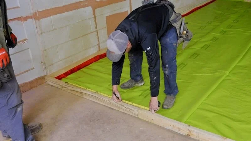
To do this, we started by marking the center of the platform at the front and then marked a line five feet from that center mark in both the left and right directions.
We then pulled a diagonal line to the back of the platform from both of those points and marked two points using an arbitrary distance, which was 23 feet in this case.
Once both of those points were marked at the back, we could mark the center point between them and, by using the diagonals to get this mark, we knew both center points were parallel square to each other.
From there, we could just pull the same measurement off of both center points to start our layout. As you can see, Erik added a screw so he could pull his tape off of this mark, and this is a great trick when you have to pull layout from the middle of a board.
Once the layout was done, we could start getting the joists installed.
Step 6: Install Joists for Platform
This was another kind of unique framing situation, as I wanted to use 2x4s as the floor joists here, so I could keep as much headroom above this platform as possible. Believe it or not, Southern Yellow Pine 2x4s can span just over 7 1/2 feet as a floor joist.
I used treated 2x4s and couldn’t find them in long enough lengths for this 20 foot deep platform, so we had to scab two boards together to get our joists.

Once the boards were connected in the middle, we could get them attached to the rim joists at either end, toenailing them at the back wall and screwing through the face of the rim joist at the front.
Once we had a few joists set in place, we could start getting them level by lining them up with the line laser. To keep the joist at the correct height, we nailed on a pressure treated foot, which both set the height and supported the joist. We let these feet run long and cut them off with a reciprocating saw, which was much faster than trying to match the angle of the floor.

Obviously, the span from those center feet to the edges of the platform was more than 7 1/2 feet. To support the joists along their length, we just continued adding more feet, adding a row towards the front edge of the platform to support that connection between the rim joist and the floor joists and then another row between those first two rows.
We added another two rows towards the back half of the platform, and the span was easily less than 5 feet in any given spot, which made this platform pretty much rock solid.
Once the left half was mostly done, we repeated the process on the right half, and this was mostly the same process, except we had to notch some of these joists around the frame straightener. The joists were mostly sitting on the ground in this area, so notching them didn’t really impact their strength.
From there, we just continued working towards the center of the platform, leveling the joists as we went and, while the guys worked on that, I came back and reinforced some of the connections with structural screws and also planed down any high spots.

To prepare for adding the sheathing, Erik and I got a layout board attached to the joists, and this locked the boards on layout here in the middle of the platform where the joists could shift left and right.
From there, we got the last few joists set and then went around and added a bunch more feet, using up most of the scraps we had generated. We also wised up and started cutting the feet flush with a circular saw, which was much easier than a reciprocating saw.
All in all, I think this technique, while maybe unconventional, ended up working out great and really simplified the process of building this platform over this sloped floor.
Once the framing was done, we added another layout board to lock in the rest of the platform and then gave the joists the old laser eye to make sure they were running straight.

They were actually ever so slightly off, so we wrestled them to the right a bit until we were satisfied with their straightness.
We also pulled a chalk line across the floor in a few spots to make sure everything was running level and, overall, we were looking really good.
Step 7: Prep and Install Sheathing
With that, the framing was done, so next, we snapped a line four feet in from the front edge of the platform. This line represented where we needed to start the second row of sheathing and you’ll see why we started with the second row here in a minute.
We added Advantech subfloor adhesive to make sure these floors don’t start squeaking in the future, and I also went with Advantech for my subfloor material. The folks at Huber were awesome enough to provide the material I needed for this project, so big thanks to them for that, as this stuff is super expensive right now.

I used Advantech for the subfloor in the tiny house and it’s been rock solid, super stiff even with the 24 inch on center layout we went with there, and I knew I wanted to use it here in the shop.
To attach the Advantech to the joists, we used 2 3/8” galvanized ring shank nails and between the ring shank nails and the subfloor adhesive, I don’t expect to ever have any squeaks in this floor.
One other really nice thing about Advantech are all of the layout marks that are printed directly on the boards. This make fastening super simple, as you don’t even have to think about your nail pattern.
We had to cut the left end piece on this second row to fit and the track saw is really the best way to cut this kind of material. It leaves a super clean cut edge and cuts really quickly through this dense material.

One other thing you can see Jason doing on this last piece is shifting the joists to match layout before I attach them to the Advantech, and this again helps to lock the joists in the correct layout.
The piece for the right end of this row was the same story, and we got it cut to fit and then nailed it in place, which completed our first full row.
From there, we got in a really good rhythm, as we could just add another row, referencing off of the previous row.
We made sure to tap the new piece along its edge to lock the groove into the tongue on previous row, and this further helps to stiffen the floor. It’s also a good idea to use a board between your sledge and the edge of the subfloor to keep from damaging the tongue.

The last row was a bit of a snug fit, but I was able to use a pry bar to lock the tongue and groove together since there was really no way to get a sledge in there.
With that, we had sheathed everything save for the first row, and that’s where we called it for day 1.
Step 8: Build Ramp for Platform
We started day two by working on a ramp for the platform, and that’s why we left that first row of sheathing off, so we could attach the wedge-shaped framing pieces for the ramp to the rim joist more easily.
I wanted to add a ramp to the front of this platform for a few reasons. First, I use carts and dollies a ton for moving around materials, and the ramp will allow me to wheel those onto this platform.
Second, I’m planning to host woodworking classes in this shop in the future, and I want the shop to be accessible so handicapped folks are able to attend my classes.
Ramp guidelines from the ADA specify a 1:12 slope ratio, which means there needs to be 12 inches of ramp length for every inch of rise. Since this platform is roughly 4 inches high with the sheathing, a 4 foot long ramp worked out perfectly here.
I started by marking a 16” on center layout for the ramp supports and I offset the layout from the joists to make them easier to install.
To cut the ramp supports, we first cut 4 foot lengths of treated material and then ripped them diagonally, from one corner of the board to the opposite corner.

By making the cuts this way, we got two ramp supports out of each piece and, considering how humpy this slab is, there were plenty accurate enough.
We attached the supports to the rim joist using a few 3” screws and, as you’ll see, the floor certainly wasn’t flat in this area. We decided the easiest way to deal with this was just to attach the end of the ramp to the slab using concrete anchors, which pulled the ramp supports tight to the floor.

Ray and Jason kept working on cutting the ramp pieces and I continued installing them on the platform until we got to where the ramp intersected the frame straightener.
We were able to just cut the ramp supports to fit towards the center of the frame straightener, as the subfloor could run over the steel in this area and end up flush with the slab.
We needed to notch the supports at the corners of the straightener, and I fastened the end pieces to the slab with concrete anchors.

The last thing we did was add a few support blocks to help keep the edge of the platform from flexing up when we attached the ramp supports to the slab later, and this just helped to lock everything in place.
Once that was done, we could sheath the last row on the main platform, which went super fast, and then we could sheath the ramp itself.
First, we tested how the transition between the panels would end up and, as it turns out, the tongue and groove still seated fine with the panel angled like this and had a super smooth transition.

I decided to forgo the subfloor adhesive and used screws on these ramp panels, just in case I ever need to change things up here in the future.
As I mentioned, I attached the bottom edge of the platform to the slab using concrete anchors and this really locked everything in place, although I ran out of anchors and was only able to install them roughly every three feet at this point.

Once that was done, the platform and ramp were officially built and, to christen them, as is now tradition after building the tiny house, I pulled out the hoverboard and cruised around on this super smooth floor.
I don’t know if there’s a more efficient way to clean an area than riding a hoverboard with a leaf blower.
Of course, the guys had to give the hoverboard a go and Erik was a pretty solid rider but Ray’s skills still haven’t improved since the tiny house build….
Needless to say, I think the hoverboard has found its new home here at the shop.
Step 9: Prep and Paint Platform
We called it a day with the Perkins at that point and next, I wanted to get this platform painted to make it look even nicer. I started by running the robovac to clean up the platform, and Nate followed that up with the blower for good measure.
Next, Nate went around and sunk any nail heads that ended up proud and he used a nail set for this. Let me tell you, it is not easy trying to drive in these ring shank nails, they have some crazy holding power.

I wanted to have a nice, grippy work area on this platform and decided to try TotalBoat’s TotalTread paint, which is a non-skid deck paint designed for boats. I figured it’d be perfect for this application, so we started by getting a coat of TotalBoat Topside Primer applied, to help with coverage and adhesion.

This primer covers extremely well, but I underestimated the amount we’d need and Nate had to use every last drop to get the platform mostly primed.
After letting the primer dry for a few hours, he applied the first coat of the TotalTread paint and it has to be rolled or brushed on as the abrasive material in the paint will damage spray gun systems.
Nate applied three coats in total and he did brush the paint into the seams between the panels, which really gave the floor a nice, finished look.

With that, we could call the platform a wrap!