
Pouring Concrete & Building Girders // Not So Tiny House Build Part 3
Learn how to create forms and pour concrete footings plus build wooden girders or beams for the tiny house foundation! Welcome to part 3 of the (Not So Tiny) Tiny House build series, where I'm building a house in the woods from start to finish!
Note: Links below are Amazon affiliate links
🛠 Tools Used On The (Not So Tiny) Tiny House Build:

How To Pour The Footers And Build The Girders Of A Not So Tiny Tiny House:
In case you missed the last part of the series, we got the layout of the building complete, including setting up a string line at grade, and also dug the holes for the concrete footings which will make up part of the foundation of this house.
Step 1: Creating The Forms For The Footings & Adding Rebar

The next step in the process was getting the forms created for the footings, as well as adding all of the rebar that was specified in the building plans.
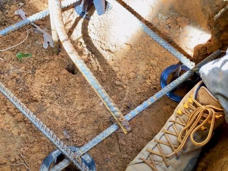
Erik and Jamie, the Perkins Builder Brothers, were on hand to help with this process and we started by getting our 10 foot lengths of rebar cut into two foot sections using an angle grinder.
To keep the rebar pieces securely in place while the concrete was being poured, we needed to tie them together with pieces of wire. We used pre-cut wire with loops at each end and used this wire twister tool to assist in tightening the wire.

After adding the wire, we could drop the rebar into the hole for the footing, setting the rebar up on these plastic rebar chairs which help to center the rebar in the base of the footing.

Once the rebar grids had been added to the footings, we could work on getting the Sonotubes set in place one foot above the bottom of the footing ut first we needed to do a little brainstorming.
Before setting the Sonotubes, we needed to go ahead and add our J-bar, which will tie the base of the footing to the Sonotube-formed pier. This particular J-bar, which Erik and Jamie picked up at the local concrete plant, had a little rebar leg welded onto the end, and we could drive that leg into the ground to help keep the j-bar in place during the concrete pour.
After driving in the J-bar, we used another wire tie to connect it to the rest of the rebar.
Step 2: Trim Sonotubes To Rough Length

To set the Sonotubes, we would first measure the rough length of Sonotube we needed, and we made sure to leave some extra length so they could run above the string line, so I could cut them to final height later.
Next, we cut the Sonotube to length with a circular saw, and these are just cardboard, so they cut really easily.
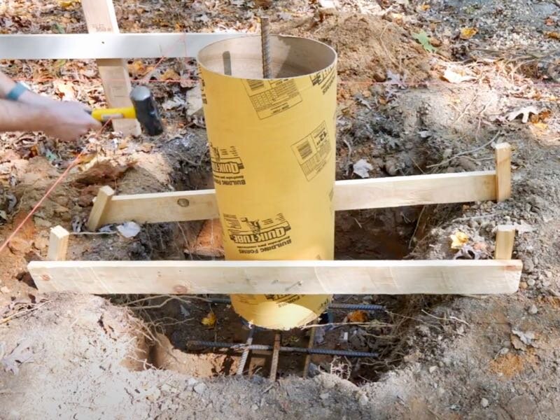
Next, we marked the center of where the Sonotube needed to be placed on our string line and then set our J-bar at that location.
We could then mark on the side of the Sonotube where it needed to meet up with the 1x4 bracing and then pre-drive some screws from inside the Sonotube, to attach it to the 1x4s.

We ended up driving longer screws from the outside through the bracing into the Sonotubes later, because it was super awkward to try to drive the screws on the inside of the Sonotube with the j-bar in the way.
After attaching the Sonotube to one of the 1x4s, we could adjust the positioning to make sure it was centered on our mark and then attach it to the other 1x4, also making sure the Sonotube was level.
We repeated this process of setting the rough positioning of the Sonotubes on the rest of the footings.

Unfortunately, the inspector came out right about then, as I had called in the footing inspection that morning, and he failed us because we didn’t have all of the footing forms completely set up.
He also mentioned the fact that the building plans specifically called out an 8” spacing on the rebar grid, which we hadn’t done, so we had to go back and adjust our spacing there as well.
Anyway, back to setting up the forms, next we drove in a stake at each end of the 1x4 bracing, so that we could more firmly attach the supports to the ground.
We screwed the bracing to the stakes, making sure the Sonotubes were level and centered in the holes while doing this, and we could also add extra screws through the bracing into the Sonotube to further secure everything.
We repeated this process on the rest of the footings, and you can see we also added some diagonal bracing on the taller footings at the right end of the building.

We called it a day at that point, and I got up before the sun rose the next morning to cut the Sonotubes to length. I got my line laser set up at grade, to the height of the batter boards and string line, and then I could get the Sonotubes cut to final length, cutting along that laser line.
Step 3: Early Morning Trimming Sonotubes To Final Height
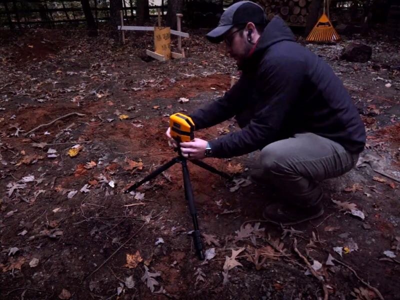
Getting to work before the sun was up really helped me see my line clearly and I cut the Sonotubes using a cutoff wheel on the angle grinder.
As you can see, as I cut through the face of the Sonotube facing the laser, the laser could actually shine on the inside of the back face of the Sonotube, making it really simple to just work my way around the Sonotube, cutting to my line.

I repeated this process on the rest of the Sonotubes and, after I had them all cut to height, I double checked my work with a string line, which ran across the top edge of the Sonotubes perfectly.
Also, I called in a second footing inspection at this point and, thankfully, I passed, as the concrete arrived later that afternoon.
Step 4: Pouring The Concrete For The Foundation Of Your Tiny House

I had never done this kind of concrete work before, so the process was a little confusing to me, but basically I was working with two separate businesses. The concrete plant, who I ordered the concrete from, supplied the concrete in their mixer truck, and then the concrete pump truck operator then ran this concrete through their pump to get the concrete into my backyard.
I ordered just over 4 yards of 3000 PSI concrete, which was specified on the plans, and I requested a 3” slump, which the pump truck operator recommended.

I had never heard this slump terminology before, but evidently it’s a measurement of the consistency of the concrete, with a higher slump number indicating thinner, less viscous concrete.
For these footings, the pump truck operator recommended a 3” slump, so the concrete would be thick enough to stay in the Sonotubes and not just flow out the bottom, displacing the other concrete in the footing base.
Anyway, after the pump truck guys got their lines connected and ran a slurry through to get everything primed, the concrete truck from the plant could start feeding the concrete into the pump.
Back on site, the pump truck operator could operate the pump with a remote, which allowed him to control the feed rate of the concrete and he could start filling the footings. He first filled the base of the footing, adding concrete until it met up with the bottom edge of the Sonotube, and then he partially filled the Sonotube.

He then moved onto the next footing, again filling the base then part of the Sonotube.
Next, I added a few more pieces of rebar in the Sonotube, both the further reinforce the Sonotube area but also to help get rid of any large air pockets in the Sonotube.

After I added the rebar, the pump truck operator would come back to top up the Sonotube, making sure it was slightly overflowing so I could screed it level.
We repeated this process on the rest of the footings, which only took about 30 minutes.
Once the footings were filled, the pump truck guys then needed to pump the remaining concrete out of their lines, something I wish I would have known beforehand, because I would have probably dug an extra hole for this residual concrete to be poured into.
Finally, after getting most of the concrete out, the pump truck operator ran a sponge through the line, to clean out any remaining bits of concrete, and this sponge comes out the other end like a rocket.
Step 5: Screeding The Top Of The Footings
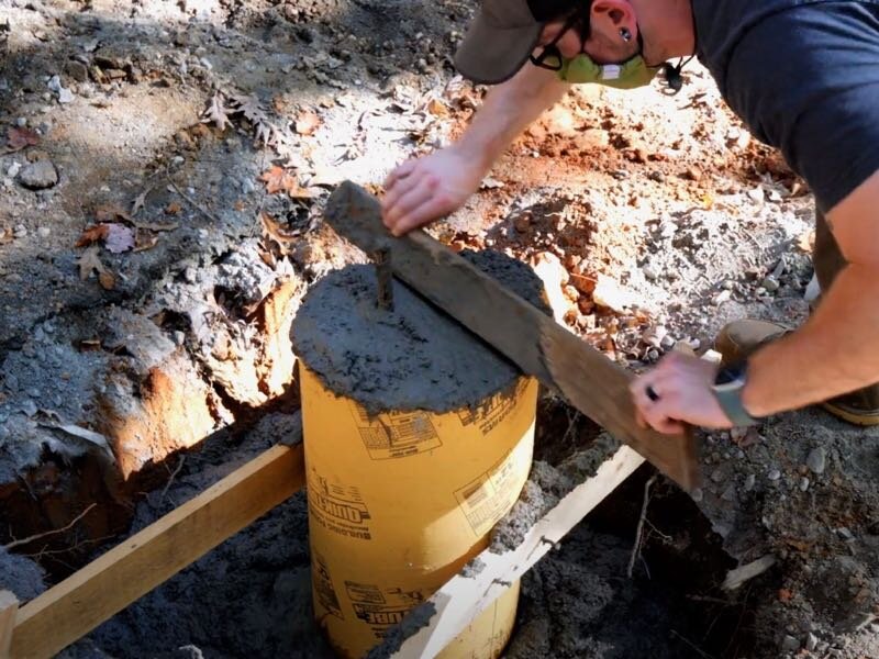
With that, the pump truck guys headed out and I could get to work screeding the top of the footings, to ensure they were flat and level. I just used a straight piece of wood to do this and made sure to saw the board back and forth to remove any excess concrete.
Having the j-bar sticking up definitely made this a little more difficult and, if I did this again, I’d go ahead and cut these pieces to length before pouring the concrete.
After all of the footings were screeded, I let them cure overnight.

Step 6: Cover The Base Of The Footings With Dirt
The next morning, the concrete was cured enough to remove the forms and then I could get to work filling in the dirt to cover up the base of the footings, which was made much easier since I still had the excavator rented.
I also moved the giant concrete boulder out of the way, and I still need to figure out what exactly I’m going to do with that thing.
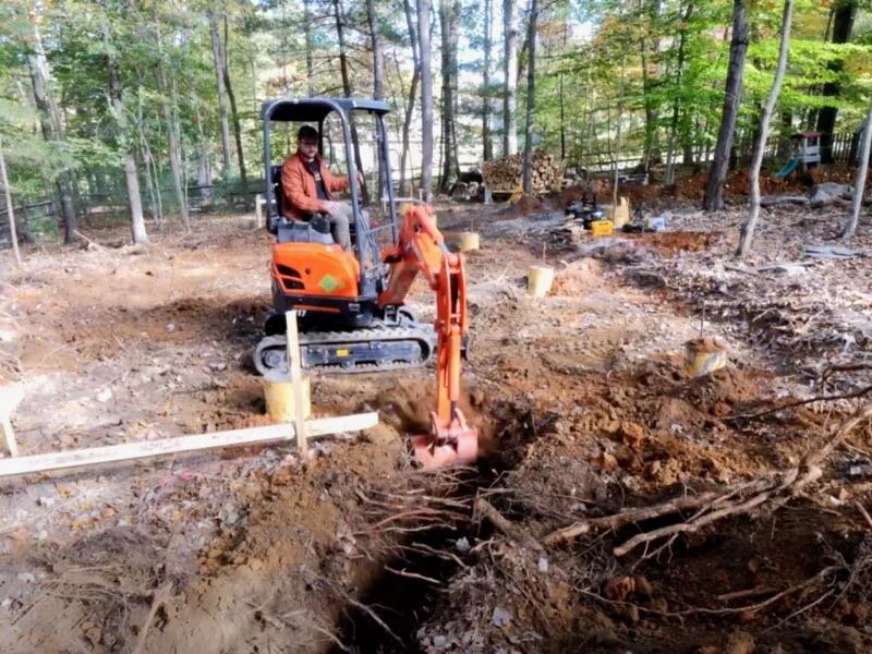
Step 7: Dig Trenches For Power, Water, And Sewer Lines
I filled in around all of the footings and then, since I still had the excavator for the rest of the day, I decided to go ahead and dig the trenches for my power and water lines, as well as my sewer line.
We’re tapping into the existing water line that supplies our main house and connecting this guest house to that water line, so first I needed to dig around in the rough area I knew our water line ran to figure out where to start my trench.
Let me tell you, this bit of hand digging definitely made me appreciate the excavator even more and, after first finding our sewer line and gutter drainage, I finally found our water line, so I could start digging the trench with the excavator.
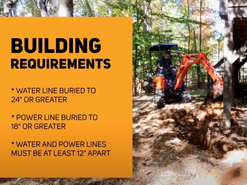
Code in this area dictates that the water line has to be dug to a depth of 24”, the power lines need to be dug to a depth of 18” in an area with no car traffic, and water and power lines have to be 12” apart.
Because of this, I dug my trench to a depth of at least 24” with a width of roughly 18”, the width of the bucket, and this gave me plenty of space for both lines. I also tried to make any turns in the trench wide enough so both the PEX and electrical conduit could run without additional fittings.
I ended the trench roughly under where the bathroom and kitchen would be, since I knew most of the water supply would need to be there, and then I could work on the sewer line.
Again, we’d be tapping into our existing sewer line, which runs kind of diagonally across our backyard, and there is a sewer cleanout at the back corner of the property where we’ll be connecting.
I dug the trench for the sewer starting in that area and actually used the excavator to help pull down a small tree that was directly in the path the sewer line would need to take.
Once again, I dug the sewer trench to the bathroom area, basically almost connecting the two trenches, and then I had to return the excavator. I’d definitely say I got my money’s worth out of this rental and burned through an entire tank of diesel, with the machine basically running on fumes as I loaded it back onto the trailer.
Step 8: Remove Sonotubes From The Piers

Anyway, after letting the concrete continue curing over the weekend, Erik and I got back to work on the foundation the following week, starting with removing the Sonotubes from the piers.
Step 9: Trimming J-bar Extruding From The Top Of The Pier Footing

Next, we cut off the protruding j-bar, which proved to be a little tricky because of all of the concrete surrounding it, but we eventually got them removed with an angle grinder and a cutoff wheel.
Step 10: Attach Base Brackets To Piers

Next, we needed to get the 6x6 post base brackets attached to the piers, and these will connect the concrete piers to the wooden girders.
We could have done this a few ways and there are post base brackets which can be cast directly into the concrete, but since I knew I’d be finishing the concrete on the piers by myself, I opted to instead use these massive ⅝” wedge anchor bolts to attach the brackets since I could drill the holes for them later.

To install the brackets, we first marked the hole location for the wedge anchor bolts, which was basically dead center on the piers, and then we could drill the hole with this massive ⅝” SDS-Max bit. Before drilling, I marked my hole depth on the bit using some painter’s tape.
I was lucky enough to have access to this beast of an SDS drill to drill these holes, and this thing was just comically large.

As you can see, this drill made insanely quick work of drilling these holes and, after drilling the holes to depth, we would then run the drill in and out a few times to remove any compacted dust from the holes.
Next, we could pound in the wedge anchor bolts and then snug down the nut to secure the bracket.
Unfortunately, the socket size for this nut was one size larger than the sockets I had on hand, so I had to use this tiny adjustable wrench to do this, but it was plenty tight to hold things in place.

To set the brackets so they were all in line, we measured off of our string line and set them all to the same distance off the line. This measurement didn’t need to necessarily be a specific number, since the floor framing overhangs the beams at both ends, we just needed the measurement to be consistent across the brackets so they were in line.
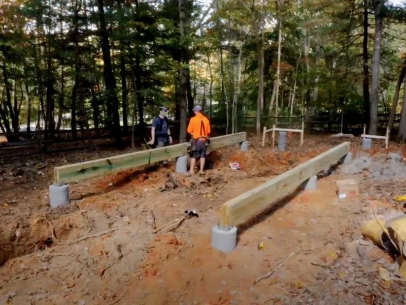
We repeated this process for the rest of the piers, setting the brackets in line, and then we could get to work building the girders or beams, but first we needed to go buy a whole bunch of lumber.
Step 11: Purchase Lumber For Tiny House Girders

These girders are made from three layers of pressure treated 2x12s and, since our footings were roughly 12 feet apart, we could use 12 foot long boards for the center sections.
We wanted the layers to overlap slightly so they were tied together well, but we also wanted both ends of each board to be supported on the post base bracket. To accomplish this, we only cut a few inches off of each board, staggering this measurement by about four inches on each opposing layer.
This allowed each board to still land on the bracket at both ends, but allowed the boards to overlap enough to create a nice, strong beam.

After cutting two boards to length, we started the process of assembling the beam by nailing these first two boards together. Before nailing, we made sure the boards were vertical using a level, so our girder didn’t end up with a slant, and we nailed the boards together using 3” galvanized ring shank nails.

This pressure treated lumber definitely wasn’t perfectly straight, and Erik had another great trick for getting these boards flush with each other. He would add a temporary nail or screw as a point of leverage and then pry on that with his hammer, flushing up two boards. Once the boards were nailed together, the temporary nail or screw could be removed and we could move on down the board.
You can also add a spacer between two boards, a speed square is perfect for this, and drive a screw in at an angle. The spacer helps give the screw more room to pull the high board into place.
Anyway, after tacking the boards together, we would go back and nail them off, adding three nails in a row vertically, roughly every 16 inches. Also, this was Erik’s first time using a cordless framing nailer, and needless to say, he was pretty impressed…

After nailing off one side, we could add the third layer and nail off the opposite side and then we had one section of the girder built.
Step 12: Attach The Girder To The Post Base Bracket

To attach the girder to the post base bracket, we used these 1 ½” connector screws which are specified by the manufacturer. These are speciality screws meant for this application, not just your regular deck screws, and I’m just mentioning this as you will likely fail your inspection if you use a different type of screw here.
We could then continue on building the rest of the girders, working out from the center of the building, until we got to the end sections of the girders. We needed to switch to 16 foot 2x12s here, since we had a longer overhang at each end of the building.
We let the boards run wild at the ends and cut them to length after assembling the beams.

Before cutting the beams to length, we needed to attach the inside face of the post base bracket to the beam, but since we used a 6x6 bracket, which had an actual inside dimension of 5 ½”, we needed to add a little filler piece here. Luckily a 5/4 pressure treated deck board was a perfect fit, actually a little on the snug side since this wet treated material was a little over thickness.
We attached the spacer to the beams using more nails and then attached the bracket to the beams using longer 2 ½” connector screws, to make up for the additional inch of material we were screwing through here.
Step 13: Cut the Girders To Final Length

Finally, we could get the girders cut to length and we started by marking out some layout lines, using a 12” speed square which we could reference off of our string lines.

After thinking about it, we decided the best tool to cut these beams would be my electric chainsaw, since it could cut through the entire beam in one pass. I was afraid it might be a little tough to get a clean, square cut here, but it was actually pretty simple to cut to my line if I took my time.
Erik of course had to try his hand at this and was equally impressed.
We repeated the process at the other end of the building and then we could check our accuracy and we were pretty darn happy with the results.

We repeated the same process on the other beam, and then we could officially call the foundation finished.