
How To Build A Shou Sugi Ban End Table with Hidden Wireless Charging
I built a modern end table featuring a Shou Sugi Ban finished base and hidden wireless charging! Thank you to Bernzomatic for sponsoring this video. Learn more about the TS8000 torch, their other torches, and accessories.
👕 Get your Build It Yourself merch! http://bit.ly/BuildItYourselfMerch
📦 Materials Used On The (affiliate):
Reclaimed White Oak
Step 1: Milling Materials

I had some leftover offcuts of this reclaimed Oak from the dining table project I built for my parents, and I wanted to build something that would use up all of those pieces. The first step when working with reclaimed material is to check for any metal debris, like nails, that are hiding in the wood, and I used a metal detector to do that.
After checking the wood and removing any of the hidden nails, I could start breaking down the pieces to rough size using the miter saw and bandsaw. I really like to rip material like this at the bandsaw, as most of these boards weren’t even close to flat. I used the jointer to flatten one reference edge before ripping at the bandsaw, but you can see how cupped some of these boards were.
Once the pieces were at their rough size, I could finish milling the boards, first getting one face and one edge square at the jointer then bringing them to final thickness at the planer. I could then rip the boards to final width at the table saw and cut them to final length at the miter saw.
Now, most of these steps could be skipped if you purchase pre-milled lumber like the stuff you’d find at your home center. Also, most lumber dealers will mill your boards for you for a small fee, and this is a great way to save yourself from having to use a jointer and planer.
Step 2: Joinery

The pieces you’ve seen me working on up until this point were the legs and cross supports, and next I needed to cut the joinery that attaches those pieces. I decided to show two different types of joinery here, as I know some people don’t have access to all of the tools I have.
First, I used dowel joinery, which is a really simple and extremely strong method for joining two boards. Using a dowel drilling jig, I drilled a matching pair of holes into the leg and cross support, and then I could do a test fit, which resulted in a tight, strong joint.
Next, I pulled out my Domino and cut similar joinery. As you can see, the Domino is a little faster and more efficient, but both joints are plenty strong.
Step 3: Leg Tapering

Once the joinery was cut into all of the legs, I could move on to adding a taper to both edges of the legs. It’s important to cut your joinery before doing this, as you don’t have nearly as much of a reference surface once the tapers are cut.
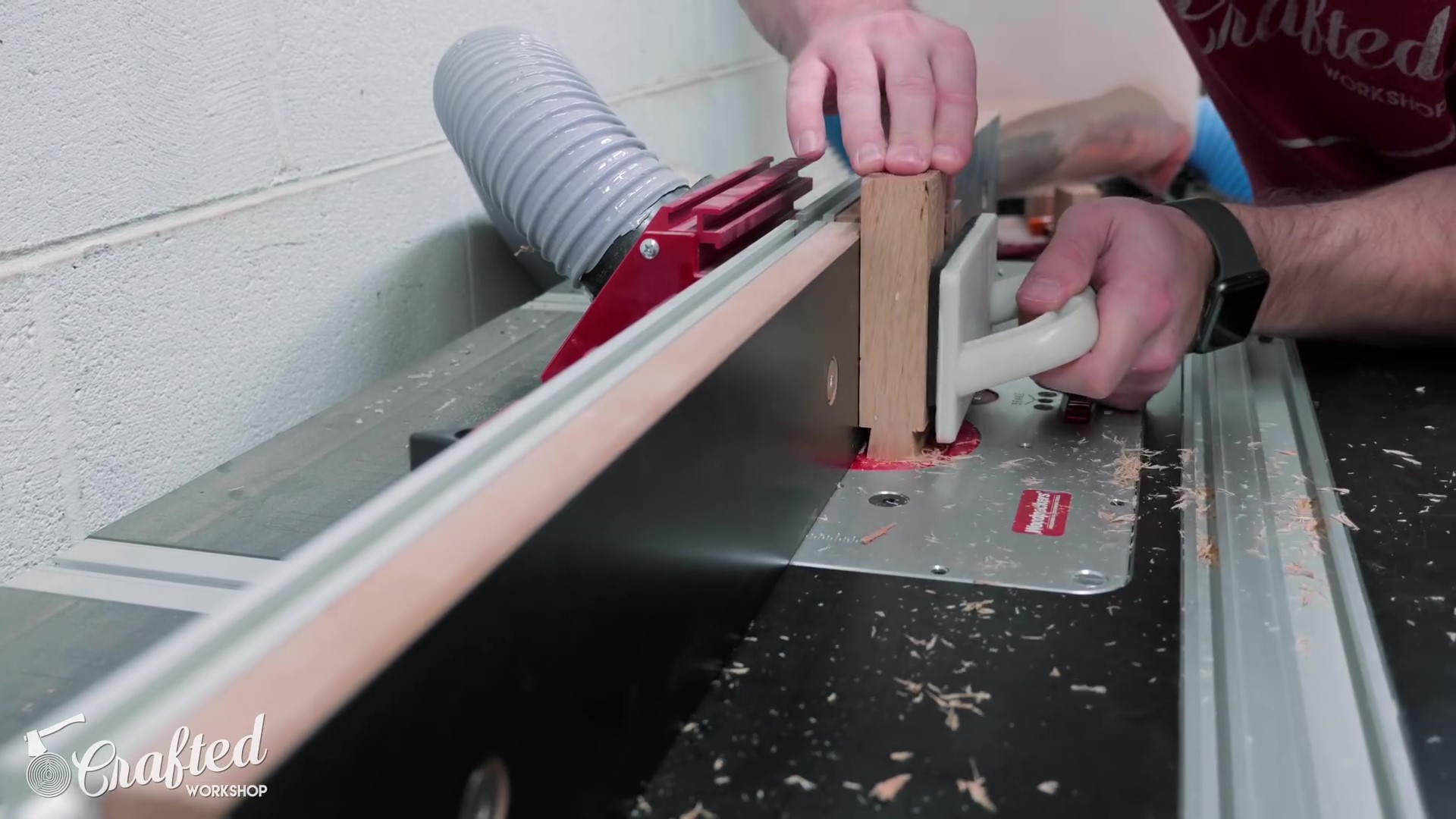
I set up my tapering jig at the table saw to remove a portion of the inside edge, the exact dimensions of which will be reflected in the plans, and then I ripped the taper onto all of the legs.
Once the tapers were cut on the inside edges of the legs, I could set up the tapering jig to cut another taper on the outside edge of the legs and repeat the process. This taper on the outside of the legs will give the legs a slightly splayed look.
Step 4: Connecting the Legs

The next piece I needed to work on was this little triangular block that connected the three cross supports. Figuring out how to join three legs like that was a real trick, and this was what I came up with.
First, I cut a few triangular blocks from some of the smaller pieces of Oak over at the miter saw. This was as simple as setting my saw to 30 degrees and making a couple of cuts. Next, I nipped off the sharp corners, as I figured they would be fragile and have a tendency to break off anyway.
Once I had the blocks cut to size, I could clear away some of the waste from the center of each of the sides. I used sliding dovetails to join the cross supports to this center block, and it’s best to remove as much waste as you can before moving over to the router table, as it puts less strain on the bit. I made sure the areas I cleared at the table saw were slightly smaller than what would be removed with the router bit in the next step.
Step 5: Routing Dovetails

Speaking of which, next I could move over to the router table. I installed this dovetail bit and set the bit height to just over ½”, slightly higher than what I removed at the table saw. I set the fence so that the bit would remove just enough material from the inside edge of the groove to cut in the dovetail shape, without removing so much as to strain the bit.
Once the bit was set up, I could then make a pass, clearing out one half of the dovetail, flip the piece around, and then make a second pass, completing the dovetail groove. One other key here is to make the width of your dovetail groove narrower than the thickness of the cross supports, otherwise you won’t be able to cut a matching dovetail on those pieces.
Step 6: Matching Dovetails
To cut those matching dovetails, I moved the fence in so only a portion of the bit was exposed and used a scrap the same thickness as the cross supports to dial in my bit setting. You want the size of the dovetail on the cross supports to be just slightly smaller than the dovetail groove in the triangular blocks. Not so tight that you have to wail on them to get them into place, but not so loose that the joint wouldn’t be strong.
Before cutting the dovetails into the cross supports, I cut the cross supports to final length at the miter saw, then started cutting the dovetails. As you can see, I used that same scrap block as a backer block behind the cross supports to avoid as much tearout as I could on that trailing edge. Oak is pretty stringy, especially this older reclaimed Oak, so I still got a little tearout, but no one will ever see these pieces so it wasn’t a huge deal.
Once all of the dovetails are routed into the cross supports, this is what they look like. You only need three of these pieces for each table, but I was building two of them, so I had six.
Next, I went ahead and drilled some countersunk holes into the cross supports at the drill press, and I’ll add screws through these holes to attach the base to the table top later. It’s much easier to drill the holes squarely at the drill press before assembling the base.
Step 7: Leg Assembly

With all of the joinery cut, I could start gluing up the pieces. First, I glued the cross supports to the legs, using both dowels and Dominos as you can see.
After the glue dried, I sanded the pieces, making sure the faces of the legs and cross supports were flush and that any burn marks from the table saw were removed, and then I moved back over to the router table to add a roundover to the edges of the legs.
This roundover makes the legs and cross supports flow together and gives the legs an almost turned look. You’ll notice that I had to temporarily add screws to those countersunk holes, as otherwise the bearing on the roundover bit would dip into those holes and mess up the roundover.
Once the roundover was added, I could sand the pieces up to 120 grit and then assemble the base. I added glue to the dovetail grooves and then added the leg assemblies. I first tried to use a strap clamp, but the tapered outside edge of the legs made the straps slide up the legs. On to plan B, I added some f-style clamps across the center of the base, and this worked out great.
Step 8: Shou Sugi Ban

After the glue dried, I sanded away any squeeze out and then I could move on to the main event, burning the table base! I didn’t really know what to expect with this whole Shou Sugi Ban process, but it was incredibly easy. I burnt the bases on top of my welding table, and it’s a really good idea to do this on a non-flammable surface. Some metal saw horses would also work well here.
I used the Bernzomatic TS8000 torch and their MAP gas, which burns hotter than propane, and the whole process went extremely quickly. One really nice thing about this torch is that you don’t have to hold down the button the whole time you’re using it, you can lock it into the on position and go to work.
I just kept moving the torch around, making sure every surface of the bases had an even char and avoided staying in one spot for too long. I didn’t really want that intense alligator char look, I just wanted to blacken the surface of the wood.
Step 9: Table Top

Once the shou sugi ban process was done, the base was pretty much ready for finish, so next I worked on the table tops. Once again, I broke down the pieces over at the miter saw then milled them square at the jointer and planer, then ripped them to final width at the table saw.
With the table top boards squared up, I arranged the boards into their final orientation and laid out marks where I wanted Dominos. Once again, dowels would work great here, as these are really just for alignment.
I cut the Domino mortises off camera, and then I could go ahead and glue up the table tops. One thing I’ve learned over the last few years is that you don’t need tons of glue squeeze out when doing these kinds of glue ups, a thin line of squeeze out indicates the joint has just enough glue without you wasting a bunch to squeeze out.
Step 10: Shaping the Top

Once the glue dried, I needed to cut the table tops into circles. There are a ton of ways to do this, and I’ve covered multiple methods, including using a bandsaw and router jig in previous videos, which I’ll link to in the cards. On this project, I wanted to make things easy and I used my X-Carve to cut the circles.
After the X-Carve finished, I cut the tabs which held the piece in place using a chisel and then moved over to the router table. I wanted to add a heavy chamfer to the bottom edge of the table tops, which really lightens the look of the pieces, and one bonus is that the chamfer bit also removes the leftover pieces of the tabs at the same time.
Step 11: Wireless Charging

Next, I could move on to adding a little extra feature to one of the tables, wireless charging. I’ve done this in a video in the past, but I used the CNC and wanted to show how to do this with more accessible woodworking tools.
First, I wanted to try removing the plastic enclosure from this wireless charger I used last time, to see if it improved the range at all. I know you can buy standalone wireless charging circuits, but I already had this charger on hand and wanted to see if this would work. The other benefit is that this charger has a built in fan to help keep the charger cool during charging.
After a bit of work, I got the plastic enclosure removed and I could move on to creating a quick template for routing in a recess for the charger.
I traced around the charger and power cord onto a scrap piece of ½” plywood, making sure to leave enough room for the ½” template bit I used to route the recess, and then I could cut the template out with the jigsaw. This doesn’t need to be perfect, as this won’t be visible from the top of the table, you just need to make sure you have enough room for the charger and power cord.
Step 12: Template Routing

After cutting out the template, I used double sided tape to attach the template to the bottom of the table top, making sure the hole for the charger was centered. Also, I love this particular brand of double sided tape, it leaves no sticky residue when you remove it and it’s incredibly strong, I’ll link to it in the video description below.
With the template in place, I could start routing. On this first pass, I didn’t really need to worry about my exact depth as I knew I’d have a lot more material to remove, I just needed to make sure I plunged deep enough so that the bearing on the template bit would ride on the template. I cleared out the entire section for the charger and went about halfway back in the groove for the cord.
I didn’t need a very deep groove coming out of the edge of the table top for the cord, but I had to plunge this bit to a certain depth to make sure the bearing was riding on the template. To get around this, I tacked a few more plywood offcuts along the edges of the cord groove area and then used that as my reference surface to finish routing the groove for the cord.
After making sure the groove was deep enough to hold the cord, I removed the template and you can see how the groove for the cord kind of steps up.
Step 13: Routing to Depth

With the template removed, the areas I already routed became the template and the bearing rode along those newly cut edges. Before continuing, I needed to set my depth stop so I could route to my final depth. I wanted to leave about 3/16” of material on the table top, just enough for the charger to work through, so I set my depth stop accordingly.
After routing to final depth, I double checked the depth with a combination square and then could attach the charger inside the recess. I used hot glue here, which is plenty strong but makes it easy to swap out the charger in the future if this technology improves, which it will. I removed the charger before finishing, so this initial hot glue was just temporary.
Finally, I could test to see if it worked, and it did. Frankly, this wireless charger has always been extremely finicky with phone placement, even when using it on the charger surface, so I will probably experiment with other chargers in the future. If you have any recommendations, I’d love to hear them in the comments below.
Next, I could sand the table tops up to 180 grit, breaking the edges on the top of the tables, and then I could move on to finishing.
Step 14: Finishing Up
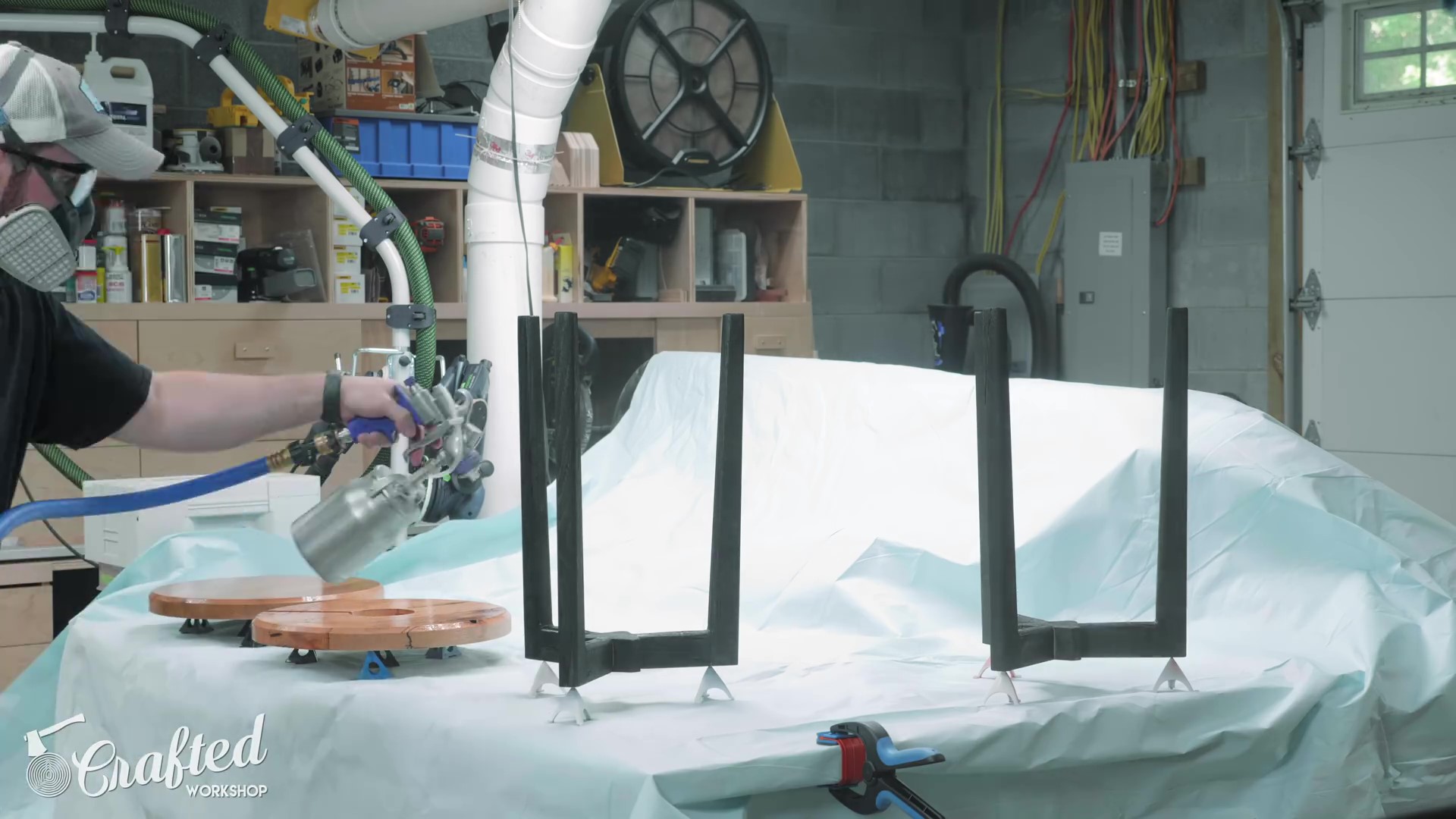
I’m sure a lot of you will ask why I didn’t use a wire brush to remove the excess char from the wood before finishing, and it’s because it didn’t seem necessary. I didn’t burn the wood that much, I really just toasted the surface, and using a wire brush removes a lot of the color from the Shou Sugi Ban process. I figured that if I sprayed on a few coats of polyurethane, the finish would soak into any of the loose bits and hold them in place, and this proved to be true.
I did hit the bases with a little compressed air before finishing, but otherwise I didn’t do anything to remove the excess char, and the surfaces are really solid, no flaking or anything like that. I sprayed on three coats in total, sanding the surfaces after the second coat.
After the finish dried, I reinstalled the charger, again using hot glue, but I also hot glued the cord into the groove this time, to keep the cord from coming loose if someone bumped into it.
Next, I centered the base on the bottom of the top, making sure to avoid the groove for the cord, and then attached the base to the top with a few 2 ½” screws. I had drilled two holes into each of the cross supports, but it turned out that one of the holes ended up going into the recess for the charger, and that second screw proved to be unnecessary anyway strength-wise.
After assembly, I could test the wireless charger again and, while finicky, it worked, and I could call this project done.