
How To Build The ULTIMATE T-Track Assembly & Outfeed Table with Systainer Storage
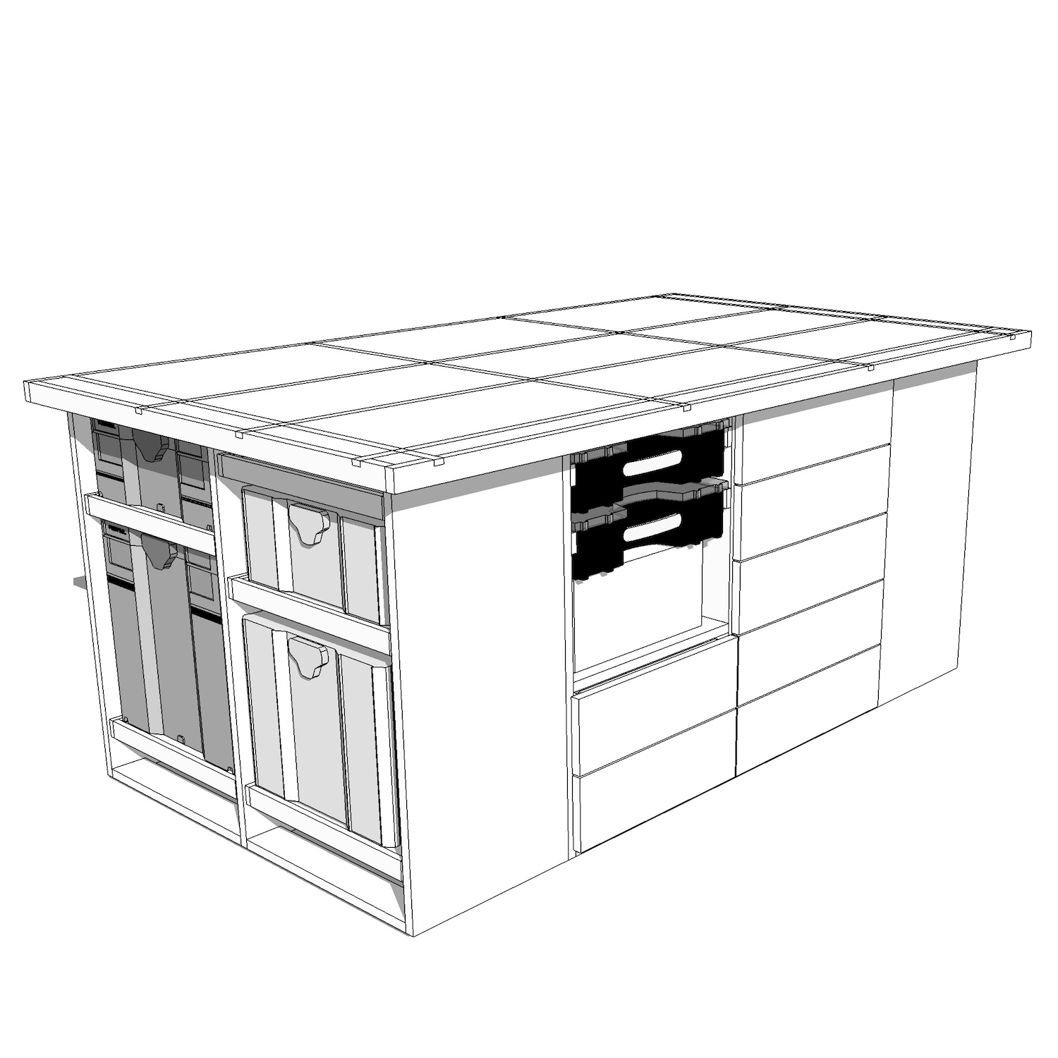
In this project video, I'll show you how to build this ULTIMATE assembly / outfeed table featuring a t-track top and Systainer storage. It's got tons of other features, including an air hose reel, screw organizers, and much, much more.
ULTIMATE T-Track Assembly & Outfeed Table with Systainer Storage Plans:
I have plans available for this build if you're interested in build one of these awesome assembly tables for yourself. The plans include a 20-page detailed PDF document including a detailed cutlist and cutting diagram. The plans also include a SketchUp file so that you can adjust the model to fit your needs.

Support This Week's Sponsors:
Purebond Plywood: http://bit.ly/purebond
Rockler Woodworking & Hardware: http://bit.ly/rocklercrafted
🛠 Tools Used On The Hardwood Flooring Installation (affiliate):
📦 Materials Used On The ULTIMATE T-Track Assembly & Outfeed Table (affiliate)
(3) 1’ x 2’ x 6’ Hardwood (for trim) : Local Home Center
(1 Gallon) Wood Glue
(~200) 1” Brad Nails
(1 lb) 1 ¼” Screws
(~200) 1 ¼” pocket screws
Voiceover Script
I started this project by breaking down the sheets of Purebond plywood into the pieces for the assembly table. For this build, you’ll need five sheets of ¾” plywood along with one sheet of ½” plywood and one sheet of ¼” plywood.
To break down the sheets, I used a combination of my track saw, table saw, and miter saw. You certainly could build this project using a circular saw, but it’d be pretty tough to get super accurate cuts.
The ¾” plywood will be used for the main cabinet carcasses for the assembly table base. The table top is also made out of two pieces of ¾” plywood glued together.
When cutting the pieces for the table top to size, I cut one piece to the final dimension and added a ¼” to the length and height for the second piece. When gluing the pieces together, I made sure there was an overhang on all four edges so that I could route the edges flush later. I assembled the table top with the work surface facing down and added glue and 1” brad nails through the bottom of the table top.
While the table top dried, I continued breaking down the pieces for the assembly table base. As I went, I made sure to number my pieces based on the parts from my cut list so that I could easily grab the correct pieces when it was time for assembly later.
Once all of the parts were cut to size, I started drilling the pocket holes which will be used to join the pieces together. I started by drilling pocket holes into the cross support pieces that will connect the two walls of the Systainer cabinet carcasses.
I made sure to offset these holes, since there will be a cross support piece on either side of the center cabinet divider, and the screws would run into each other if the holes aren’t offset.
After drilling the holes into the cross supports, I added pocket holes to the back edge of the cabinet sides as well as the center divider. These holes will be used to attach the cabinet back to the sides.
Next, I started assembling the Systainer cabinets. First, I attached the cross support pieces in each corner, making sure to orient the pocket holes so that the spacing was consistent. I added glue and two screws per corner. I made two of these assemblies for each Systainer cabinet.
Next, I added the center divider onto one of the assemblies, again adding glue and screws.
With the two assemblies complete, I then attached the two halves to each other. You can see here why the pocket holes in the cross supports needed to be offset. Otherwise, the screws would have run into each other in the center divider.
When using pocket holes, it’s really important to clamp everything in place before driving the screws. Otherwise, the parts will want to slip around and will most likely end up misaligned.
To finish the Systainer cabinet, I attached the back panel using the pocket holes I drilled previously. Make sure to check for square at this point, things will be permanent after attaching the back panel.
Here’s the finished Systainer cabinet. There are two of these cabinets, so repeat these steps to build a second identical cabinet.
Next, I moved on to building the center cabinet which attaches the two Systainer cabinets and forms the center of the assembly table. You can see here how the pieces come together.
First, I attached the bottom panel to the two Systainer cabinets, and then drilled pocket holes in the center divider and back panel.
Next, I attached the center divider to the bottom panel, using the cross supports as spacers to make sure the divider was centered. I also made sure the front of the divider was flush with the front of the bottom panel.
Once again, the center divider is attached to the cabinet sides with these cross support pieces. Again, make sure the pocket holes are offset at the center divider.
Next, I attached the back panel to the bottom panel along with the center divider to finalize it’s placement before attaching the back panel to the cabinet sides. If any of this is confusing you, I do have plans available for this build that are a lot easier to follow. It’s pretty difficult to get shots inside the cabinet while it’s being assembled, sorry about that.
With that, the cabinet assembly is done. Once the glue dried, I added these Rockler leveling feet to each corner of the assembly table base, and also added a few more feet to the center section of the base.
In addition to the leveling feet, I also added these Rockler Workbench Casters to the assembly table. I wanted to be able to move the table when necessary, but I wanted it to be rock solid the rest of the time. These casters are perfect for that application, since the workbench will be resting on the leveling feet when the casters aren’t engaged.
With the shell of the table base done and mobilized, I moved on to working on the drawers. The drawers are made of ½” plywood for the drawer box sides, ¼” plywood for the drawer bottoms, and ¾” plywood for the drawer fronts.
I keep drawers for shop furniture pretty simple. First, I glued and brad nail the sides together, making sure to keep everything flush.
Next, I flip the drawer over and add brad nails to hold the bottom to the sides. This also locks the drawer into square.
With the drawer temporarily assembled with brad nails, I come back with 1 ¼” screws, adding two screws per corner and 8 screws on the bottom. This makes for an extremely strong drawer and you don’t lose any drawer capacity like you would with a drawer bottom housed in a groove.
Next, I installed the drawers. This has not traditionally been my favorite task in the shop, since it’s really receptive and usually pretty finicky. That said, I just got one of these Rockler drawer slide jigs and it definitely makes things a little easier.
To install the slides, I marked the location of the bottom of the slide on the sides of the cabinets. Next, I put the drawer slide in the jig, making sure to seat the slide securely against the front of the jig. Next, I either held or clamped the jig in place, depending on how the cabinet was arranged, and then drove in two of the drawer slide mounting screws.
With two screws in place, I removed the jig and added one more screw to the slide. Rinse and repeat for the rest of your drawer slides.
To install the slide on the drawer, I marked the location of the slide on the sides of the drawer, centering the slide on the side of the drawer. Next, I attached the slide with three screws.
To install the drawer, pull the slides out and slide the drawer into place. The drawer needs to be pushed pretty firmly to lock the slide in place, but then it’s good to go. I just kept repeating this process until I had all of my drawers installed.
With the drawers installed, I moved on to building and installing the Systainer trays. These Systainer trays are based on a design by the Poplar Shop, and I’ll have a link to his video in the video description below. They’re extremely simple, just a piece of ¾” plywood for the bottom with ½” plywood as the sides.
The bottom is attached to the sides with 1” pocket screws, and the correct setting for the pocket hole jig is the ⅝” setting on the Kreg K4 jig. This took a little research to figure out, so I figured I’d mention it.
After drilling all of the pocket holes, I assembled the tray using glue and 1” pocket screws, making sure to clamp my pieces in place along the way. I built nine of these trays in total, even though I currently only own six Systainers. I figured having a few extras on hand if I expand my collection would be much better than having to go back and build more of these later.
Installing these trays was basically the same as installing the drawers, except I did run into one small issue when going to install the slides. I failed to account for the bolts from the caster plates when coming up with my tray spacing, so I had to rearrange things slightly to make it work.
If I were to do this again, I’d probably add a block to the outside of the cabinet and use lag screws instead of the bolts included with the caster plates.
Off camera, I added the little blocks to the back of the trays, and these just keep the Systainers in place when you close the trays.
With all of the drawer slides behind me, I moved on to adding a few other accessories to the assembly table base, the first of which was an air hose reel.
I thought it’d be pretty awesome to have a hose reel as part of the assembly table, so that I’d always have air accessible while I’m working. This hose reel has 50 feet of hose, so it should reach basically anywhere in my shop. I’ll use one of the drawers below the reel to store my air tools and accessories.
Another big part of the assembly table was effective storage for my screws. My current drawer is a total mess with zero organization and, since all of the screws are in boxes, I can never tell when I’m running low just by looking in the drawer.
I found some screw storage boxes and figured it’d be easy to build in a little area to house them, similar to what Adam Savage did with his Sortimo boxes. I added these little plywood rails but forgot that I was supposed to build them out of ½” plywood. I just planed the two strips down until the screw organizers would fit.
The last pieces to add to the base were the drawer fronts, which were simple enough to install. I cut a few spacer strips from scrap plywood and clamped the drawer fronts in place while adding a few screws from the inside of the drawers. I cut an additional ⅛” thick strip to space the drawer fronts from one another and just worked my way up until I had all of the drawer fronts installed.
With basically all of the parts of the base installed, I moved on to the table top. First, I wrestled the top up onto the base, which wasn’t that easy considering the weight.
Once the top was in place, I centered it on the base, leaving two inches of overhang on either end and three inches of overhang on the front, and then fastened the top to the base using 1 ½” screws from below. It’s important to use screws that are short enough so that the t-tracks won’t be blocked later, hence the 1 ½” screws.
Now that the top was firmly in place, I could get to work on it. First, I routed the edges of the work surface flush with the bottom piece using a flush trim bit on my router. You can see how the edges end up perfectly flush with this method, something that would be difficult to achieve if you tried lining up the two pieces during the initial glue up.
Next, I added the trim to protect the edges of the table top. I used some Hard Maple that I had on hand, but you could just as easily buy 1x2s from your local home center instead. I jointed one each of the board then ripped a few strips from the board at just over ¾” thick.
After ripping the strips to rough thickness, I planed them to their final thickness of ¾”. This also removes all of the burning left by the table saw.
Next, I jointed one edge at the jointer and then ripped the trim to its final width of 1 ⅝” at the table saw. I left the strips a little wider than necessary so that I could leave the trim overhanging slightly when attaching it to the table.
To install the trim, I took a measurement from the table and then cut the piece to length at the miter saw. I then added glue to the inside face of the trim and attached it using 1 ¼” brad nails. Again, I made sure to leave the trim a little proud on the top so I could sand it flush later.
Speaking of which, after the glue dried, I sanded the trim flush using 80 grit sandpaper. I added roundover to the edges of the trim using an ⅛” radius roundover bit on my trim router.
Next, it was time to route the grooves for the t-tracks.
Once the depth was set on the router, I went ahead and routed the first groove. I routed all of the grooves in one pass, but it probably would have been better to do it in two, although I was left with a very clean groove even going to full depth on the first pass.
I did forget to add a sacrificial board to either end of the groove on this first pass, and this resulted in a little bit of blowout at either end of the groove.
I did a test fit of the t-track and it was fitting pretty snug, so I decided to take a second pass, just to widen the groove slightly. This made the fit snug but manageable.
Here, you can see me routing the second groove on one of the sides of the table top. You can see the sacrificial block that I’ve added using some double sided tape. This completely eliminated any blowout.
With the two sides done, it was time to route the grooves in the center of the table top.
On my first pass using the plywood as the straight edge, I didn’t account for the flex towards the center of the plywood strip. This left me with a slightly sloppy groove, not the end of the world but not something I needed to repeat.
On the second groove, I added double stick tape to the center of the plywood strip, and you can see how cleanly the t-track fits into the groove by eliminating the flex from the plywood.
The last two grooves in the table top were along the short length of the top, so I could use my track saw track as my straight edge, and this was a lot easier since it is completely stiff and didn’t need any tape added.
With all of the grooves routed in, I sanded the table top up to 120 grit and broke any sharp edges on the base, then I could apply a few coats of finish. I used General Finishes High Performance and sprayed it on using my HVLP system. I really only applied finish to help protect the top from glue and other finishes, but I figured I’d add finish to the base while I was at it.
The last step in the build was to install the t-track into the grooves in the table top. This was a pretty straightforward process, especially since I got these intersections from Rockler. You certainly could make these yourself out of regular t-track, but these intersection kits massively simply things.
To install the t-track pieces, I pre-drilled holes and drove in #6 screws. The screws are included with the intersections but aren’t included with the regular t-track sections. I’m assuming this is because Rockler doesn’t know how thick the top you’re screwing into is, so they let you decide on the screw length yourself. I went with 1” long screws.
To cut the t-track sections to length to fit between the intersections, first I measured each piece individually since the measurements will vary slightly based on the intersection placement. To cut the pieces to length, I used my miter saw. Aluminum is a really soft metal and the miter saw cuts it extremely easily and leaves a clean cut.
Once cut to length, I pounded the t-track flush with a dead blow mallet and then pre-drilled the holes and drove in a few screws. One other thing I wish I’d had during this t-track installation was a self-centering drill bit. Drilling the holes would have been a lot faster if I didn’t have to worry about centering the hole perfectly to keep the t-track from shifting.
Once all of the t-track sections were installed, the assembly table was finally done!