
Building My Shop, Part 2 : Electrical, LED Shop Lighting & Sound Proof Insulation
In part 2 of my shop build series, I'll walk you through the rough-in electrical wiring, installing LED shop lighting, and adding soundproofing insulation.
Note: The links below are Amazon affiliate links

Electric And Insulation Installation:
Step 1: Choose The Lighting You Want

For the shop lights, I went with 12 of these 96W LED fixtures from American Green Lights, plus one additional 72W fixture towards the back door.
American Green Lights LEDs, which you might remember seeing me install in my last shop, have a super high CRI, or color rendering index, rating, which means their color accuracy is nearly perfect. This is extremely important for me, as skin tones look better on camera, paint and finishes look more true to life, and overall the space is just be more pleasant to work in compared to fluorescent or cheaper LEDs.
Also, the number of fixtures I ended up using wasn’t a random guess, as one of the services American Green Lights offers for free to their customers is a custom lighting simulation, where you send them a layout of your shop and they recommend the number of lights you’ll need, as well as where those lights should be installed.

This is an incredibly valuable service, especially for a shop like mine, which doubles as a video production studio.
Step 2: Prepare Ceiling For Lighting Installation

To install these fixtures on the concrete ceiling of the shop, Justin and I first got to work installing these 2x4 strips, which spanned the gaps between the ribs of the ceiling. We installed these due to the fact that the lights weren’t going to line up with the ribs when spaced as needed.
We used concrete anchors to install these strips, and ran them at 3 feet from the wall on the left side of the shop and 4 feet on the right side, which was based on the types of tools that will be on each wall. We also used a line laser to make sure the 2x4s were run in a straight line, rather than relying on measuring off of the wall.
Next, we marked the locations for each light, to make sure they were spaced evenly. First, we used a laser measure to determine the distance from the partition wall to the back of the shop, and then divided the space evenly for the lights. The first light started 3 feet from the partition wall and then there was roughly 5 feet between each light fixture.

We first marked these locations on the floor of the shop, then used a line laser to transfer the marks to the strips on the ceiling.
To prep the fixtures for installation, we reamed out the knockouts in the fixtures slightly with a step bit to accept snap connectors, then installed the snap connectors, which just press in and are locked into place. These connectors were used because we used MC cable for the wiring for the lights, which meant we didn’t need to add any additional EMT or conduit.
Step 3: Installation Of Fluorescent Lighting

Next, we could hang the fixtures, which went really quickly since we already marked the locations. We also marked center marks as we went along, to make sure the fixtures were nicely centered on the 2x4s.
To run the wire to the fixtures, we first used this MC rotary wire cutter to strip back the metal housing from the cable. We could then run the wire through the connector and snap the MC cable in place. In this case, we actually hung the fixture after running the cable, but we ended up hanging the rest of the fixtures first as we found it easier.
Also, to be clear, we didn’t actually wire any of the lights, we just ran the wire and let the electrician handle all of the actual wiring.

And here’s how the lights looked once they were hung and wired. The wiring to the panel is temporary, just to allow us to have some light in the space while we work on the build out, and I’ll show you where the “home run”, or the wire leading back to the panel from the light switch, will actually come from later in this video.
Step 4: Installing Can Lights In Office Ceiling
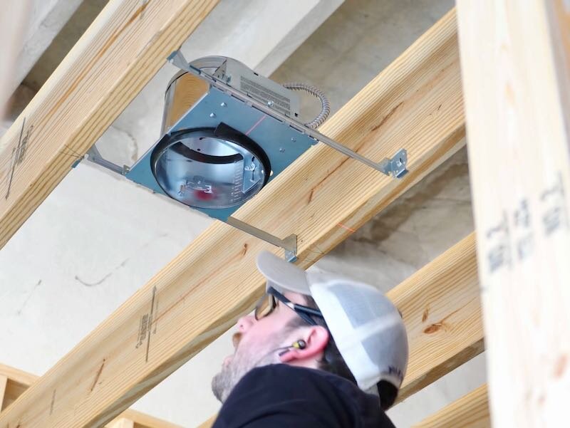
Fast forward to after framing and we could get the can light housings hung in the office. I went with American Green Lights LED retrofit inserts for the actual lights, but I picked up the housings themselves locally. And I know some of you were asking why we used such heavy duty joists over the office, and that was to provide enough space to add these can lights.
Once again, we called on the line laser to help us layout where to place the housings in the joists and we made our marks based on these lines.
The housings were a little finicky to install as they were kind of flimsy, but they just nailed directly into the joists. The hanger bars are adjustable to accommodate any variances in joist spacing and then the housings can be slid on the hanger bars to adjust the exact location of the cans between the joists.
As you can see, the locking screw for the cans left a bit to be desired, as they still moved around even after they were supposedly locked, but they will be locked into place when we get the ceiling paneling installed later.
The last bit of lighting was in the area about the photo wall and front door, and we did this off camera as it was just more of the same process of hanging the fixtures.
Step 5: Electrical Wiring In Stud Walls

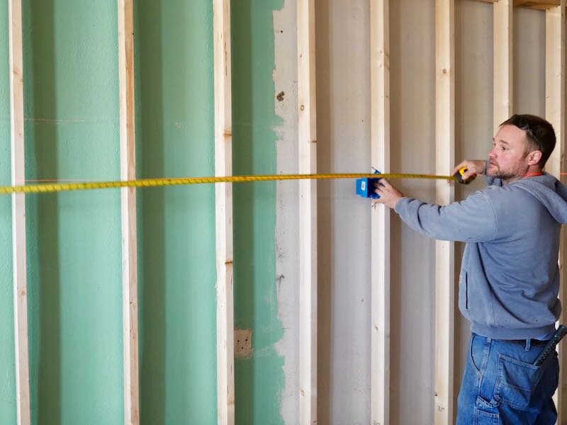
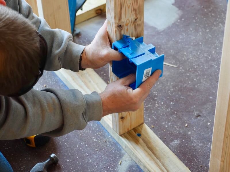
With the lighting hung, we could move on to the wiring, and the first step was to get the boxes mounted on the walls. We decided to place these at 5 feet off the floor in the shop, which would put them above most tools, work tables, or even sheet goods leaned against the wall.
We made a mark at 5 feet then set up the line laser at that mark, and then we could easily line up the laser with the top of the boxes as we installed them. These boxes just nail into place and they go up really quickly.
For all of the 120V outlets, we used 2-gang boxes, which will house four outlets. For the 240V outlets, we used 1-gang boxes since they will all have single outlets.
The 120V outlets were spaced roughly 6 feet apart along the length of each shop wall, while the 240V outlets were placed more strategically based on the exact tool locations.
Since the right wall of the shop was covered up with stuff, we decided to go ahead and wire the left side of the shop as well as the office next, since the wiring for the office ran through that left wall anyway.
First, we marked out locations for the holes for the wiring, again using the line laser. This step was probably overkill, but having all of the holes perfectly aligned made pulling the wire later extremely easy.
After marking the holes, we came back and drilled the holes using a 1 inch spade bit. The hole size will depend on how many wires you’re planning to pull through each hole, but 1 inch ended up worked well for up to about 3 or 4 pieces of 12/2 Romex.
Also, we made sure the holes were more towards the back of the studs, so that the screws we used to hang the plywood later wouldn’t risk hitting the wires.
Once the holes were drilled, we could start pulling wire. We started with the 10/2 wire, which was used for the dedicated 30 amp circuits for my dust collector and new Powermatic 12” jointer which will be arriving whenever this build out is finished.

This process was much easier with two people, as Justin could unspool the wire as I pulled it through the holes, which kept it from getting kinked.
I would pull each run back to the panel, leaving about 6 feet of excess, and then we would cut the wire and wrap it up and over the outlet box. We also labeled each end of each wire as we went, to make sorting through the bird’s nest of Romex at the breaker box later much easier.
The 220V outlets were all on dedicated circuits with a mix of 30A and 20A circuits, depending on the tool requirement. The 110V boxes had two total circuits on this wall of the shop, with the circuit running to every other box. This way, if I load up two sets of outlet boxes that are next to each other, there shouldn’t be any issue since they’ll be on two separate circuits.
Once all of the wire was pulled, we would go back and run the wire into the actual boxes. To do this, we would knock out one or two of the trap doors in the box, depending on how many wires we had, and then we could pull the wire through. The trap doors are pretty tight, so it can be a little finicky getting the Romex into the box, but it’s incredibly secure once it’s fed through.
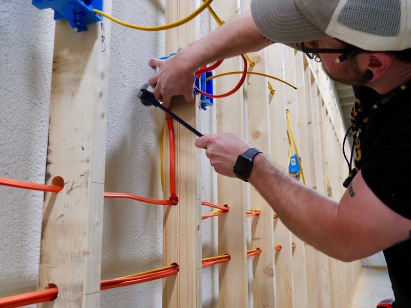
After pulling the wire into the boxes, we would go back and add staples to secure the Romex against the studs. You need staples within about 8 inches of each box and 12 inches of each opening, but it’s always better to add more than you need.
Step 6: Office
Next, we worked on the office area. The outlets in the office were placed about 16 inches off the floor, so that they would be underneath any of the desks in the space.
We also added another 2-gang box for outlets on the outside wall of the shop, so I can plug in my soft boxes for the photo wall, as well as a 1-gang box for a light switch to control the lights in the front photo area.
Getting wire up to the office was the same process as before, drilling more holes then pulling more wire. We only had two circuits in the office, one for the outlets and one for the lights, so there wasn’t a ton of wire to pull.
We did go ahead and pull a home run for the shop lights, so I could have a switch on the shop side of the partition wall, which will control both banks of shop lights independently.
We had to use a metal box for this light switch, as we had to use MC cable for the lights. Again, we didn’t actually wire the switch to the breaker, as we already had the one bank of lights directly wired to the panel so we could have lights during the build out.
Back to the office, we finished up by running wire to the box for the light switch as well as the can lights. We also ran more wire off camera up to the exit sign at the front door, as well as to those lights in the photo wall area.
Step 7: Wiring The Other Side Of The Shop

With the left side of the shop and the office done, we could move on to the right side of the shop, which first required getting wire over to that side of the shop. The easiest way we figured we could get the wire over there would be to run more MC cable, and we needed two runs, one for a dedicated 30A 220V circuit and the other for the rest of the 120V outlets on that side of the shop.
To get the wire across to the breaker, we ran more 2x4 strips to allow us to run the MC cable along the ceiling. We would have attached the cable to the drywall but there didn’t seem to be any studs in the uppermost part of this wall and we didn’t feel like dealing with that.
After getting the wire over to the right side of the shop, we just repeated the process of hanging the boxes and running wire. Once again, we used metal boxes for the first box in each of these circuits, since we were using MC cable. Since there were only two circuits on this side of the shop, this process went much more quickly.
Step 8: Electrician Inspection

With all of the wire pulled, my electrician could come in to make up all of the boxes, which included stripping back the Romex, connecting all of the ground wires for each circuit, as well as any other wires that needed to be connected, and then rolling up the wire and stuffing it back into the boxes. He also added fire caulk wherever we had wire running vertically through the blocking or top plates, which is a code requirement.
This process has to be completed prior to the rough-in inspection, which was the next step in the process, which I obviously didn’t get any footage of. My electrician had to call in the inspection with the county using my building permit number, and then the inspector came out to verify the wiring had been done properly. This rough-in inspection had to be completed before I could move on to covering up the wiring with insulation and any other wall coverings.
Step 9: Installing Insulation
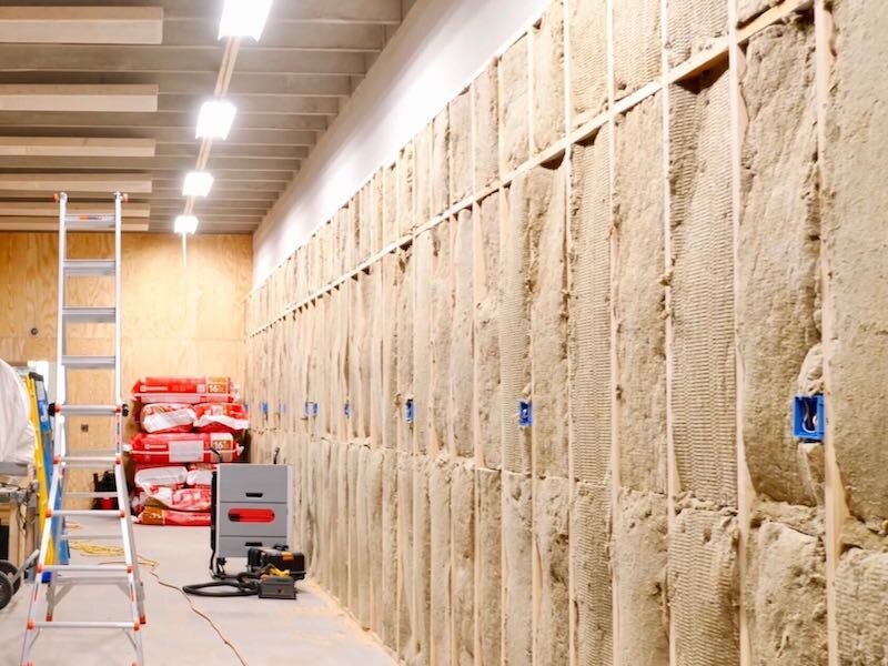
With the inspection done, this phase of the electrical was done, since none of the outlets or breakers will be wired until after the walls are up, so next it was time to add insulation.
Now, I wasn’t adding insulation in this space to provide any R-value since I was adding it to interior walls. Instead, I was adding insulation to control sound, since I have neighboring tenants I don’t want to anger with my noise and there was also a ton of echo in the space which is obviously bad for video.
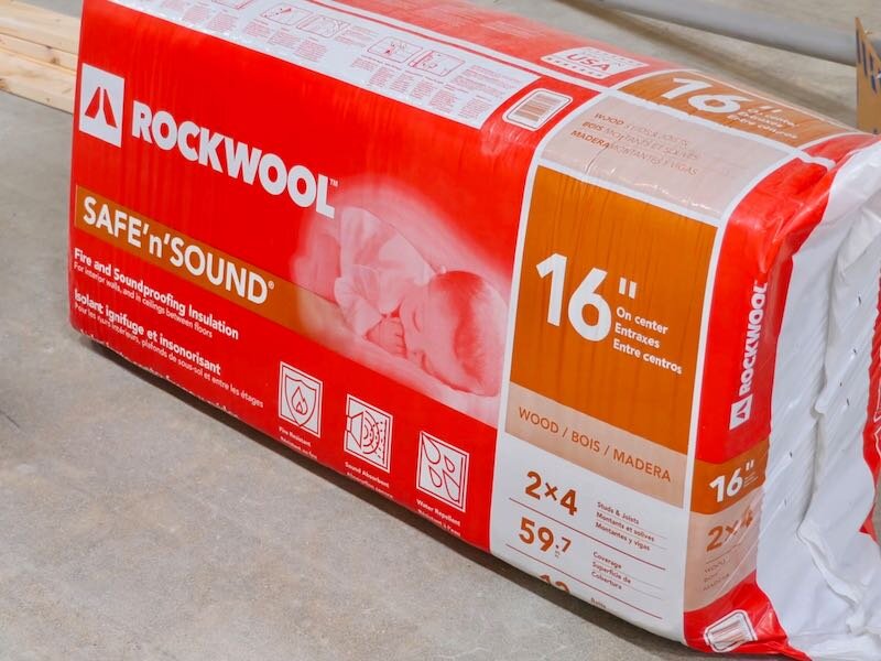
I went with a product called Rockwool Safe ’N’ Sound, which is marketed as a soundproofing insulation, but Rockwool also has a ton of other benefits, including being incredibly fire resistant due to the fact that it’s made from natural stone and recycled materials. It is also water repellant and is completely resistant to mold and mildew.

Before installing the insulation, Justin and I actually built and installed 10 of these really simple acoustic panels, which we made using leftover 2x4s, landscape fabric, and more of the Safe ’N’ Sound insulation. I’ll have a full video on how we made and mounted these panels later in this series, so stay tuned for that.
Due to time constraints, I ended up hiring a local insulation company to help install the Rockwool and they did an awesome job. They insulated the entire space in a little more than half a day, where it would have taken Justin and I at least multiple days to finish.
That said, the process of installing Rockwool is extremely simple and is definitely an easy DIY project if you’re looking to soundproof your garage, home theater, etc.
To install it, you need to cut around any obstructions, such as outlet boxes or wiring, with a serrated knife and then stuff the insulation between the studs. You can see that these guys ended up cutting the bats in half to go around the wiring and then came back with small strips to fill in the gaps.

Also, since Rockwool is denser than traditional fiberglass insulation, it stays in place more easily without as much sagging, so you’re able to run the insulation without fighting it.
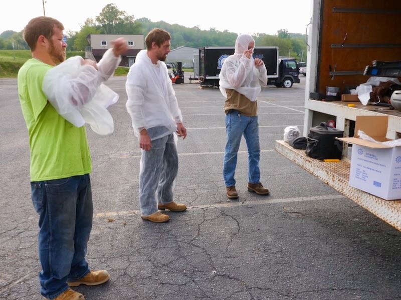
You do definitely want to wear full safety gear when installing Rockwool, as with any other insulation. This includes a respirator and at least long sleeves and gloves, if not an entire suit like these guys had on. This stuff is extremely itchy if you get it on your skin or breathe it in, so definitely be safe when installing it.
With the insulation installed, I could call this part of the shop build series finished!